
Dear all, after a few months of testing we are extremely happy to release the new clean desuicide / security programing method for Capcom's CPS2 hardware.

This guide is the result of almost two years of work by an small group of arcade enthusiasts to unravel the secrets of the security implementation found in one of the largest and most popular arcade platform systems. Thanks for this work it is now possible to fully preserve any CPS2 systems as original hardware.
Over the coming weeks additional details about the CPS2 hardware internals will be released providing unseen insights into how Capcom implemented security.
Thanks to everyone who has helped test and validate this release throughout the summer, special thanks to Bill DeLeo, Jeremy Walski, Leonard Oliveira and rtw.
Capcom CPS2 Security Programming Guide
This document will guide you through the basics of preparing your setup and testing the new clean desuicide method on any of the known CPS2 board revisions. You can find a pdf copy of this guide and code on the following link: https://github.com/ArcadeHacker/ArcadeHacker_CPS2
What's needed
Arduino programmer hardware
- Arduino Uno (with USB cable)
- LCD Keypad Shield
- Pin strip (at least 7 pins)
- Dupont cables (at least 8 x female-female, and 8 x male-male)
- Grabbers / Clips (at least 6 pieces), or you can also use a JST NH 6 pin connector instead of grabbers, pins are part number SHF-001T-0.8BS or SHF-002T-0.8BS.
- Power supply capable of 5 volts @ 1.5 amps or more, eg: arcade or ATX PC power supply.
- Female power supply molex with cables
- Soldering iron and solder
CPS2 motherboard tools and supplies
- Torx security screwdriver set including at least size T20
- 3.6v batteries ½ AA type
- Battery case holder axial
Software
- Computer with Arduino Software
- ArcadeHacker_CPS2.ino Arduino program file
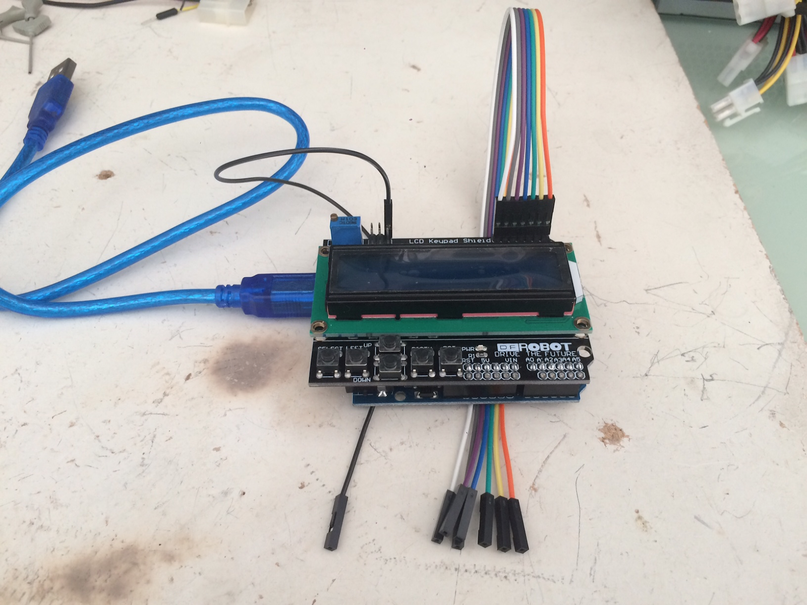
Assembling and preparing your Arduino programmer
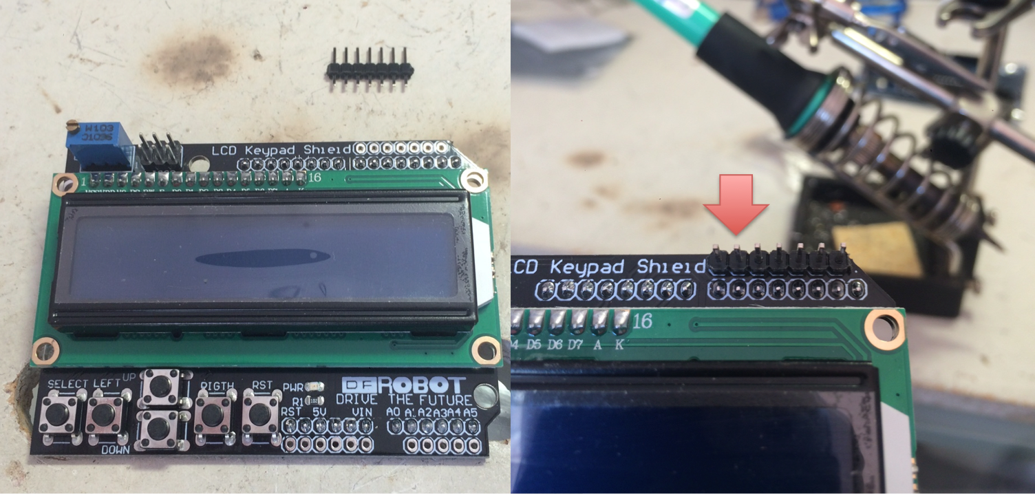
- Solder the 7 pin strip to the top right most socket of the LCD Keypad Shield
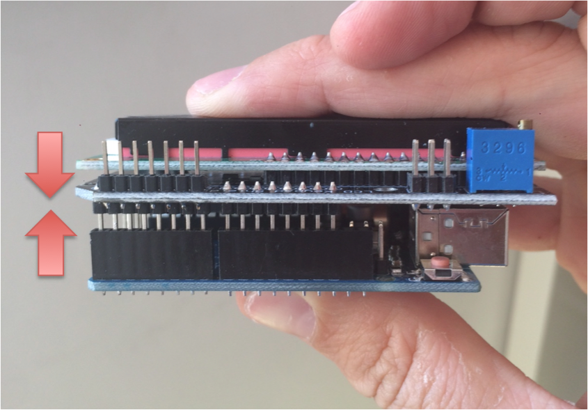
- Assemble the Arduino Uno and LCD Keypad Shield together
- Download and install software for your OS from https://www.arduino.cc/en/Main/Software
- Connect your arduino to your PC via USB
- Open the ArcadeHacker_CPS2.ino file in the Arduino environment.
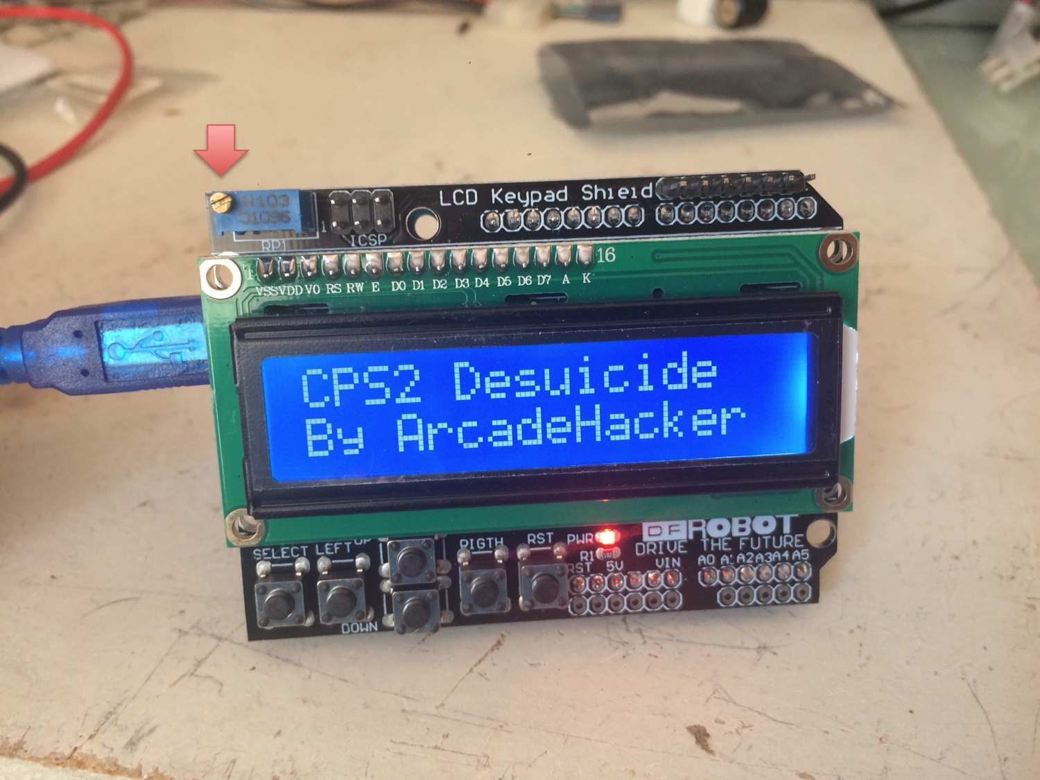
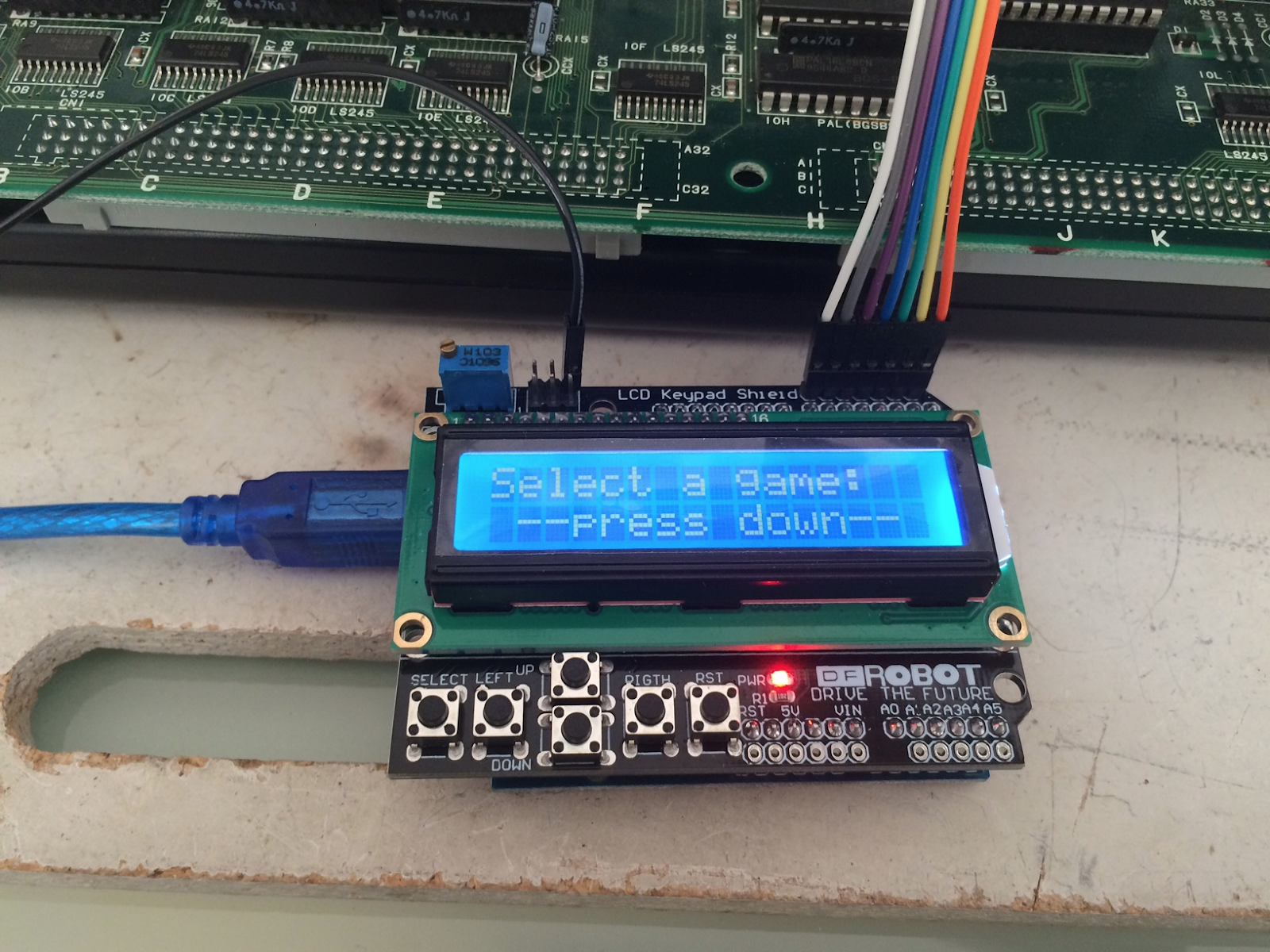
- Compile and Upload the sketch to the Arduino, next boot sequence should display what's shown below. If you can't see anything you may want to double check the screen contrast setting.
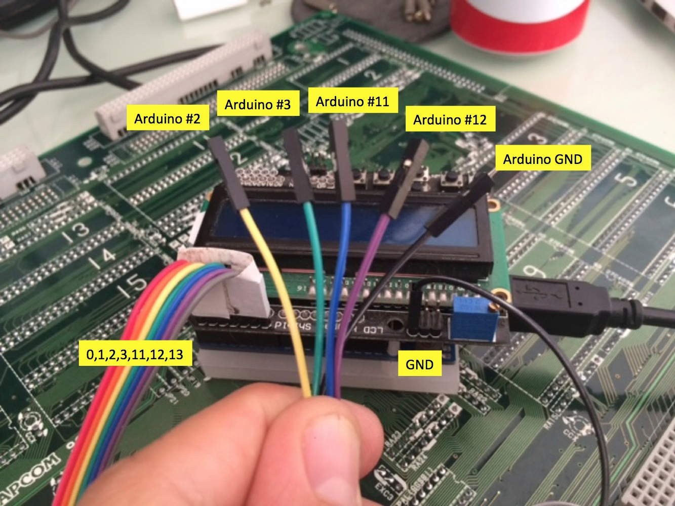
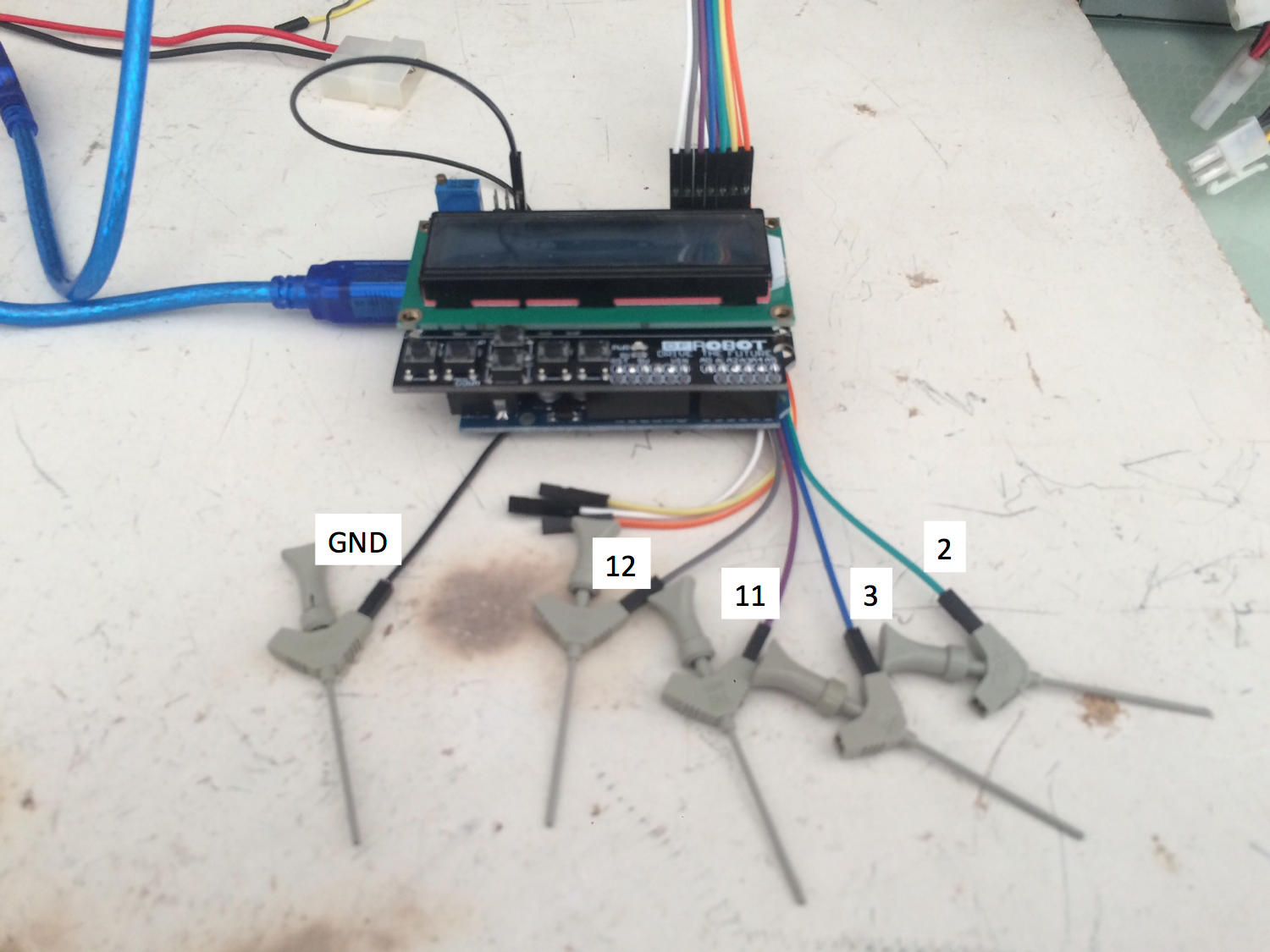
- Locate digital pins 2, 3, 11, 12 (top right) and GND (top left icsp connector) on your LCD Keypad Shield. Label them if possible.
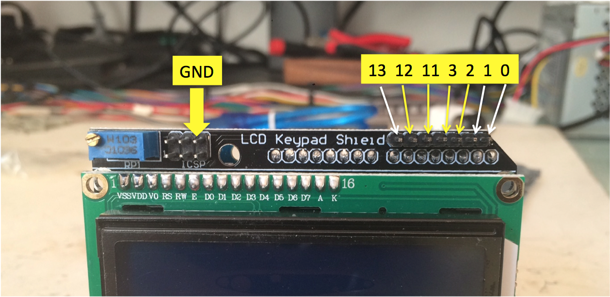
- Connect the dupont cables to the pinout as shown above. Label them if possible.
Assembling the CPS2 target power cable
Attach two female dupont ends to the female molex power plug.

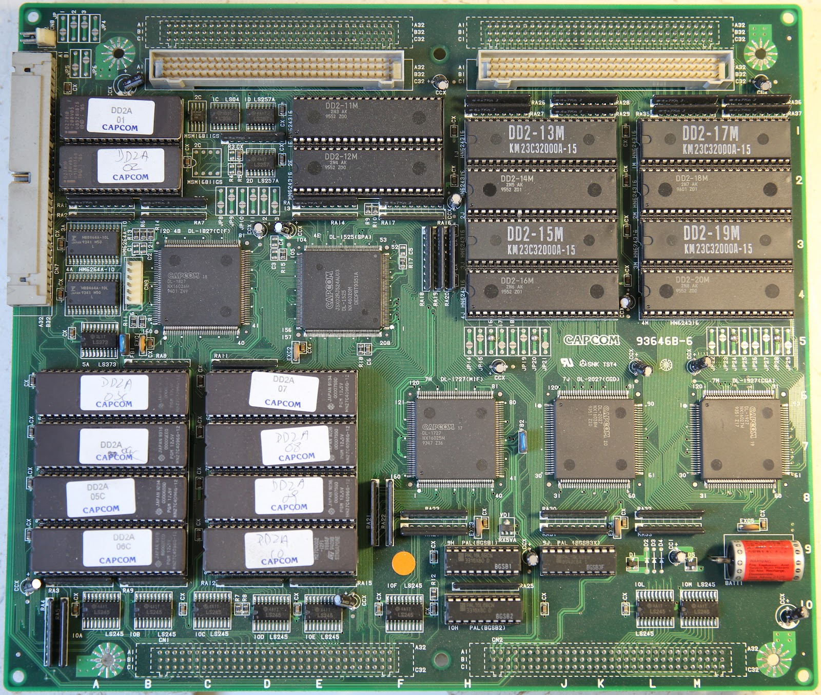
Identifying your CPS2 B board type
There are several revisions of PCB. These are the relevant ones:
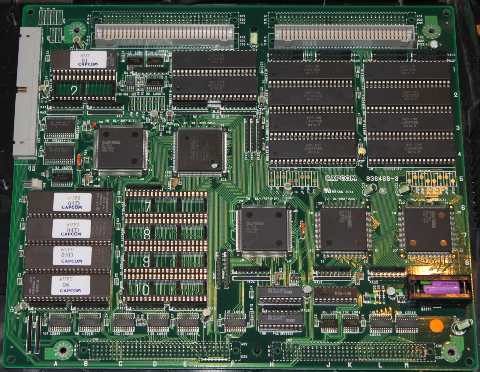
93646B-3:
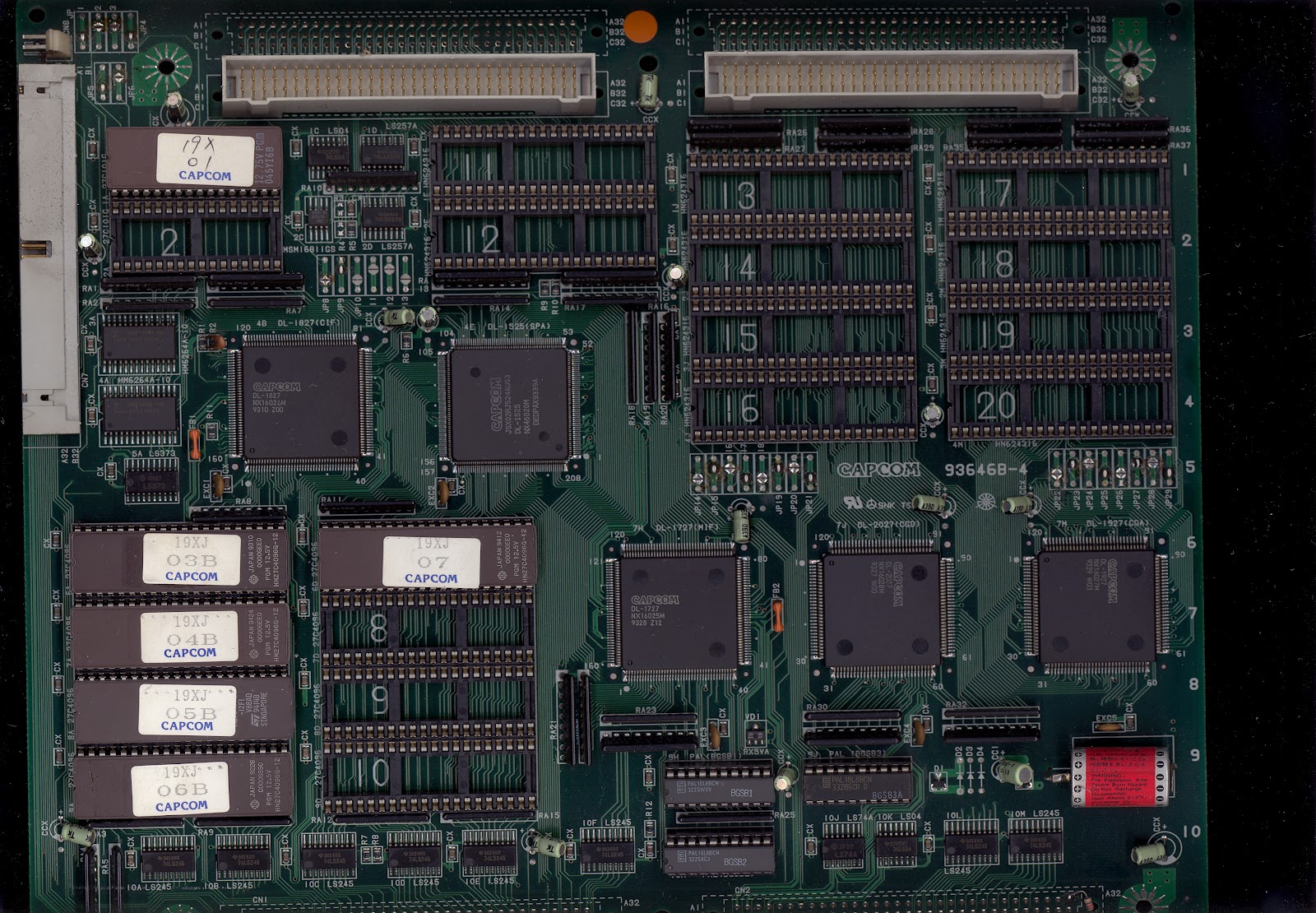
93646B-4:
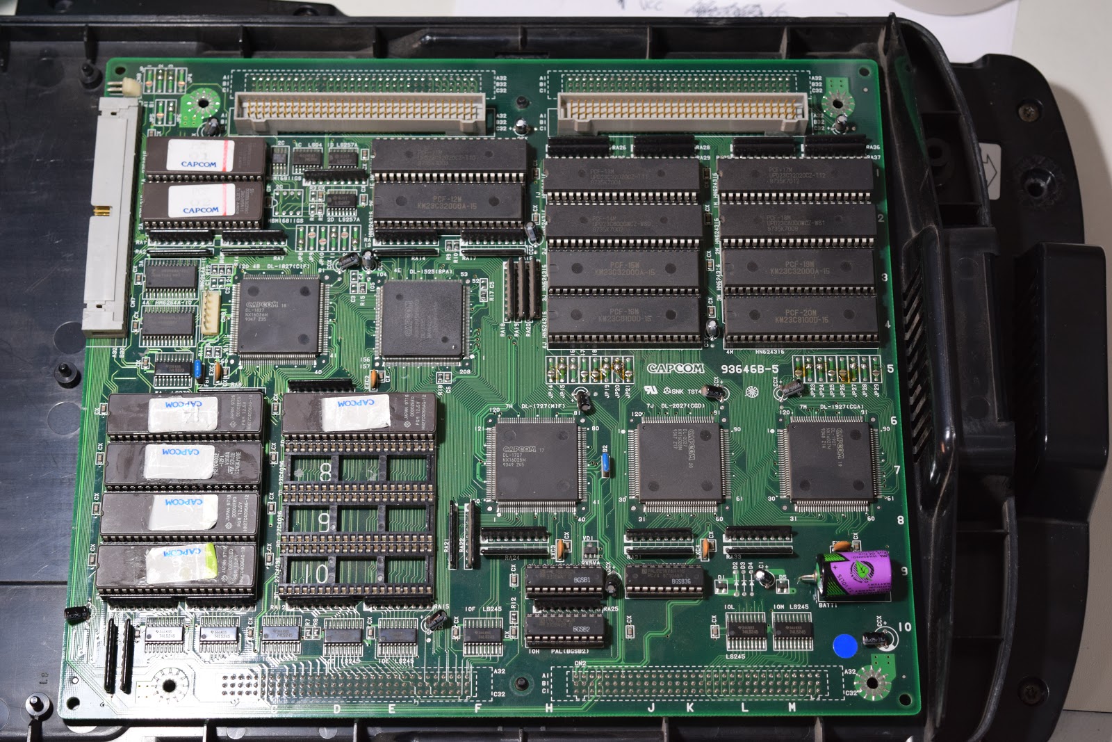
93646B-5:
93646B-6 and 93646B-7:
97691A-3 and 97691A-4 (Black case, single board):

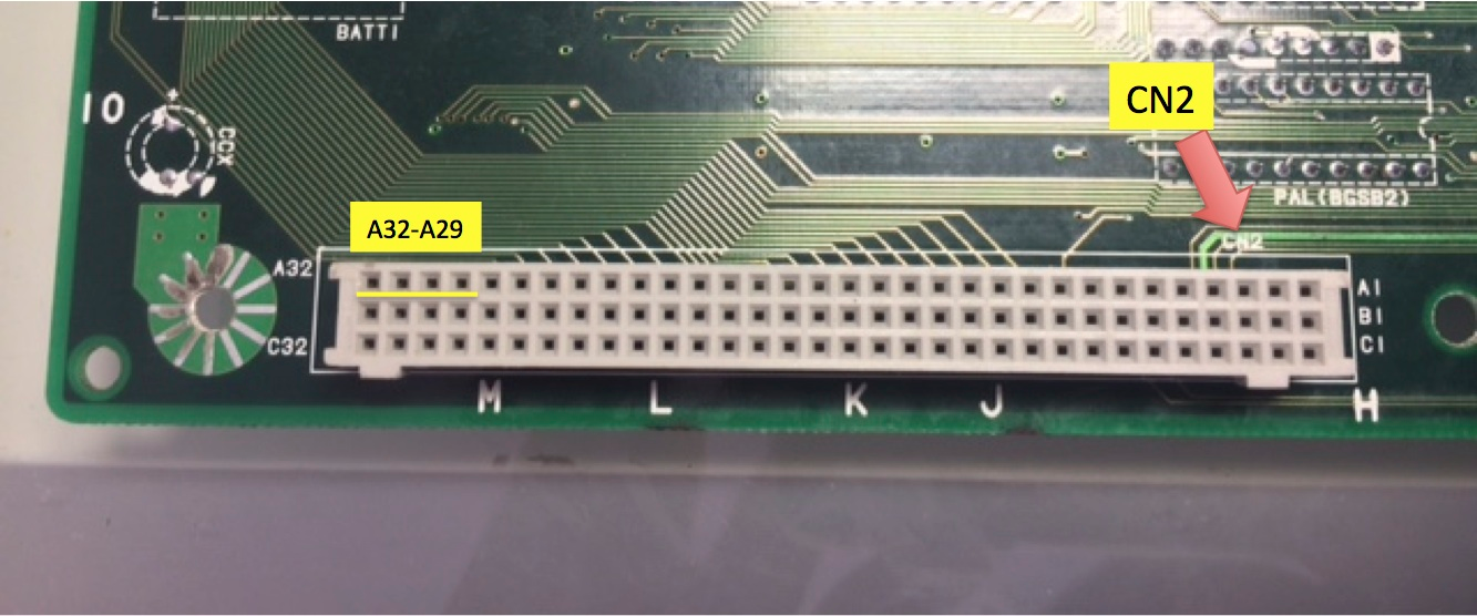
Pinout for board revisions 93646B-3 and 93646B-4
CN2 interface pins:
DATA Arduino #2 → CN2 A32
SETUP1 Arduino #3 → CN2 A30
CLOCK Arduino #11 → CN2 A31
SETUP2 Arduino #12 → CN2 A29
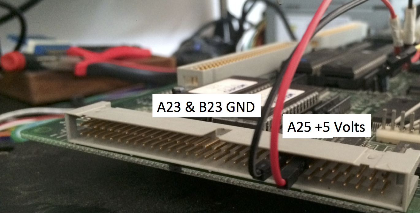
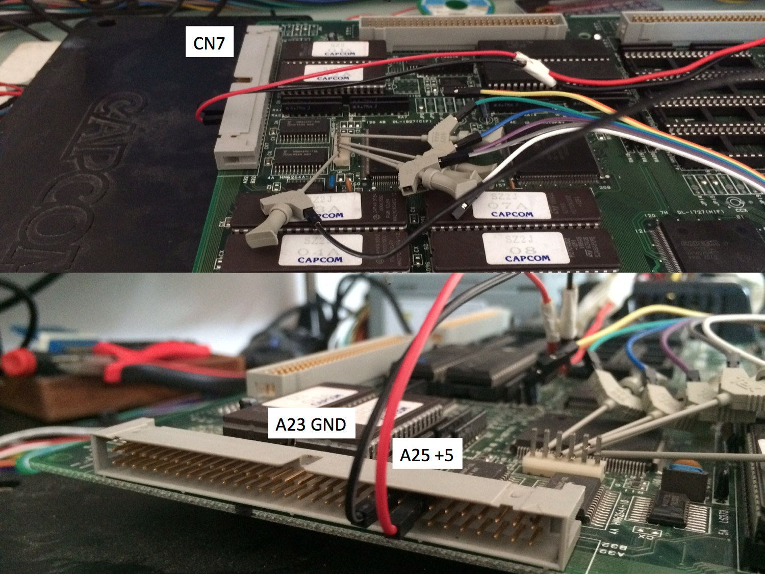
CN7 power pins:
+5V Power supply → CN7 A25
GND Power supply & Arduino GND → CN7 A23
GND Power supply & Arduino GND → CN7 B23
Pinout for board revisions 93646B-5
CN9 interface pins:
DATA Arduino #2 → CN9 #2
SETUP1 Arduino #3 → CN9 #3
CLOCK Arduino #11 → CN9 #4
SETUP2 Arduino #12 → CN9 #5
CN7 power pins:
+5V Power supply → CN7 A25
GND Power supply & Arduino GND → CN7 A23
GND Power supply & Arduino GND → CN7 B23
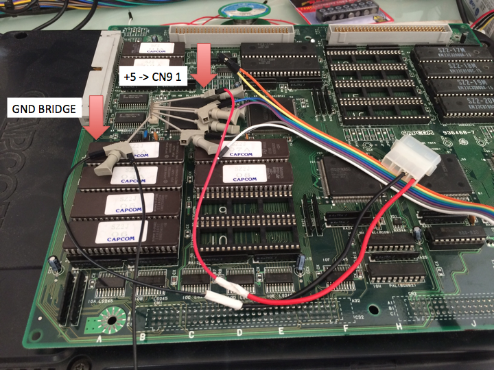
Pinout for board revision 93646B-6, 93646B-7 and 97691A-3
CN9 pins:
+5V ---------------- → CN9 #1
DATA Arduino # 2 → CN9 #2
SETUP1 Arduino # 3 → CN9 #3
CLOCK Arduino # 11 → CN9 #4
SETUP2 Arduino # 12 → CN9 #5
GND Arduino GND → CN9 #6
Preparing your CPS2 B board
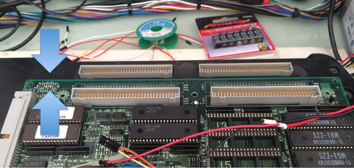
- Open the CPS2 B Board plastic case using the Torx Security T20 screwdriver head (the photo below does not apply to revision 97961A-3 "all in one black")

- Identify your PCB revision and check the battery voltage

- If needed replace the battery with a fresh spare, fit a battery holder when possible

Desuiciding revisions 93646B-3 and 93646B-4
- Connect your hooking cables to the corresponding outputs of the arduino programmer (2, 3, 11, 12 & GND)
- Connect all pins to CN2 following the order described below.
DATA Arduino # 2 → CN2 A32
SETUP1 Arduino # 3 → CN2 A30
CLOCK Arduino # 11 → CN2 A31
SETUP2 Arduino # 12 → CN2 A29
GROUND Arduino # GND → CN2 C32

- Connect power cables to CN7 A23 & B23 (GND) and A25 (+5)
- Connect the molex connector to the power supply (power supply off!)

- Make sure the CPS2 A board and B board are disconnected from each other
- Turn on the power supply connected to your CPS2 B board, then power up your Arduino programmer (plug the USB cable to a USB power source, eg: your computer)
- Follow the on-screen instructions and program the game configuration you wish to upload. Use the up/down/right/left buttons to advance through the game options.
- Once programmed, disconnect power to the Arduino programmer followed by switching off the main power supply to your CPS2 B board
- Disconnect all arduino and power supply wires connected to the PCB
- Assemble the CPS2 A and B boards together and test for results. If unsuccessful take your time to review your setup before attempting a new keyload.
Desuiciding revisions 93646B-5, 93646B-6, 93646B-7, 97691A-3, 97691A-4
- Connect the ic clips to the corresponding outputs of the arduino programmer (2, 3, 11, 12 & GND)
- Connect all grabbers to CN9 following this order. You can also use a JST NH 6pin connector, pins are part number SHF-001T-0.8BS or SHF-002T-0.8BS depending on your wire gauge.
DATA Arduino # 2 → CN9 #2
SETUP1 Arduino # 3 → CN9 #3
CLOCK Arduino # 11 → CN9 #4
SETUP2 Arduino # 12 → CN9 #5
GND Arduino GND → CN9 #6
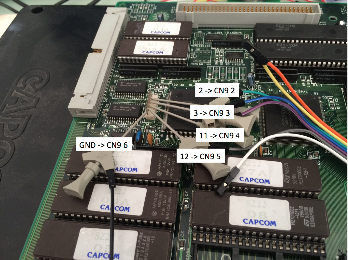
- [Revisions 93646B-6, 93646B-7, 97691A-3 only] Attach the power cable as shown below. GND connects to the existing arduino grabber.
- [Revision 93646B-5 only] Connect power cables to CN7 A23, B23 (GND) and A25 (+5)
- Connect the molex connector to the power supply (power supply off!)
- Make sure the CPS2 A board and B board are disconnected from each other
- Turn on the power supply connected to your CPS2 B board, then power up your Arduino programmer (plug the USB cable to a USB power source, eg: your computer)
- Follow the on-screen instructions and program the game configuration you wish to upload. Use the up/down/right/left buttons to advance through the game options.
- Once programmed, disconnect power to the Arduino programmer followed by switching off the main power supply
- Disconnect all arduino and power supply wires connected to the PCB
- Assemble the CPS2 A and B boards together and test for results. If unsuccessful take your time to review your setup before attempting a new keyload.
Hands-on video tutorial by Artemio
https://www.youtube.com/watch?v=ulIi9B74HMs